24 Oct LED Puzzle Game
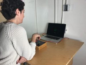
For the Physical Computing Midterm, I worked with Brandon Newberg and created a puzzle game using 4 LEDs and 4 switches. The goal is to turn on all 4 lights by pressing a combo of switches. The reward for completing the game is a p5 animation created by ITP students for the player to enjoy.
Demo
Inspiration
The idea stemmed from a puzzle game in Resident Evil 3. In this particular game, the protagonist , Jill, has to turn on a designated light by pressing buttons, and she has to successfully do that for three rounds in order to open a safe. The last time I played Resident Evil was more than 10 years ago. I forgot most of the game, but the memory of this specific puzzle is still fresh in my mind. There must be something interesting in it otherwise I would have forgotten about it.
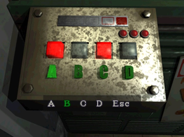
What is interesting and what is confusing
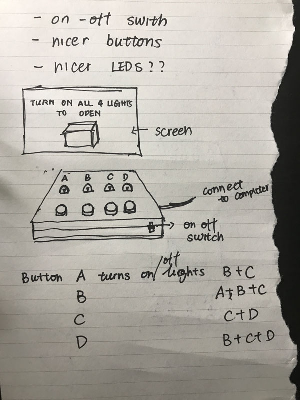
One of the reasons why I find the puzzle interesting is probably the initial confusion it causes. Even though the lights and switches are mapped in a way that implies a one-to-one relationship, the switches are actually programmed to each turn on a combo of lights, instead of the one light right in front of it as one would imagine. For our version of the puzzle, I want to keep a little bit of that initial confusion, but also make the game easier to understand for the players. We decided to change the end goal from lighting up one LED to lighting up all LEDs, which is a more intuitive way of thinking.
Process
It took me a while to figure out the relationship between the switches and the lights. I wanted to create a pattern that can possibly be detected without being too easy to figure out.
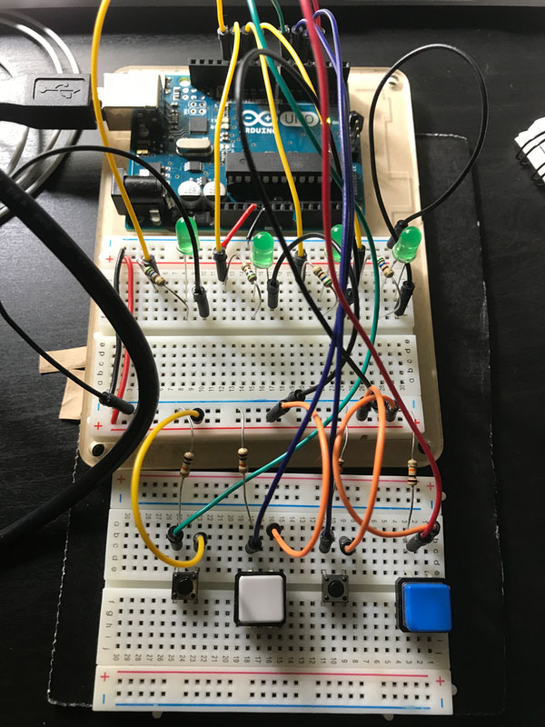
Below is the first prototype from last week. In my Serial Blogpost there are more details.
Brandon and I then went ahead to reexamine the layout of the game. Below are the two versions prototyped.
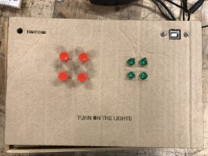
In terms of a user’s mental map of the switches and lights, the two prototypes are similar. With either one, a player would assume the switches and the lights have a one-to-one relationship. However, the linear layout (on the left)may create more confusion because it looks more conventional and creates a more direct correlation between the elements. We eventually decided to go with the square layout (on the right), which is better-looking and presents itself more like a game rather than a row of light switches on a wall.
Reward, Countdown and Distraction
To retain player’s interest, we created a library of p5 sketches provided by our fellow ITP students. Every time the player wins, a beautiful p5 sketch will appear on screen as the reward. The library is still growing. For now we have sketches from Roland, Alden, Katya, Michael Blum and Michael Fuller. Thanks guys!
To add to the intensity of the game, we added a 60-second countdown, as well as a “flash warning” function once the clock is below 20 seconds. The flash function also acts as a distraction for the player.
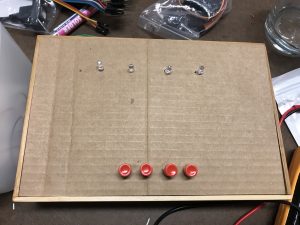
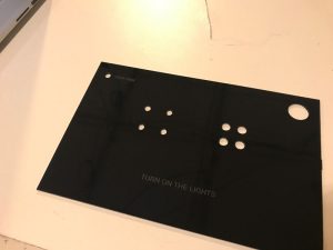
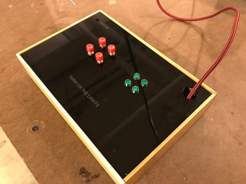
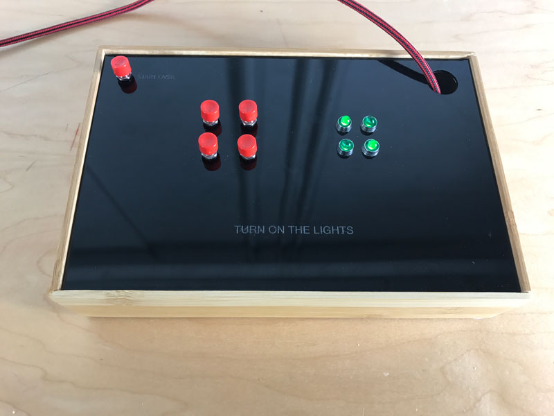
Putting it in a box
The last step was to create a more refined prototype using panel mounts and customized enclosure. In order to simply the circuit, Brandon came up with the idea of using Arduino’s internal pullup resistors for the switches instead of wiring pulldown resistors to them. We slightly modified the Arduino code for this to work, specifying the pullup pins and reversing the signals coming from the switches. We went through some difficulties wiring the LEDs (we each broke a leg of an LED trying to bend it to the desired position), but eventually succeeded in fitting everything in the box.


No Comments